Ask Latest Price
Verified Supplier
6 Years

Shenzhen Olinkcom Technology Co.,Ltd
Customer demand oriented, Technological innovation, Build a first-class design and manufacturing enterprise in the optical transceiver industry.

Add to Cart
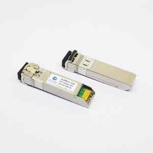
Cisco SFP-10G-SR Compatible 10GBASE-SR SFP+ 850nm 300m Transceiver
Product Features
●Supports up to 11.3Gb/s bit rates
●Duplex LC connector
●Hot pluggable SFP+ footprint
●850nm VCSEL transmitter, PIN photo-detector
●Up to 300m on 50/125um MMF(2000MHZ.KM)
●Low power consumption, < 1W
●Digital Diagnostic Monitor Interface
●Optical interface compliant to IEEE 802.3ae
●Electrical interface compliant to SFF-8431
●Operating case temperature:
Commerical:0~70°C
Industrial:-40 to 85 °C
Applications
●10G Base-SR/SW at 10.3125G
●10G Fiber Channel
●Other optical links
Product Descriptions
Olinkcom’s OLSP851XL-C(I)DS3 Enhanced Small Form Factor Pluggable SFP+ transceivers are designed for use in 10-Gigabit Ethernet over MultiMode fiber. They are compliant with SFF-8431,SFF-8432 and IEEE 802.3ae 10GBASE-SR/SW. The transceiver designs are optimized for high perform-ance and cost effective to supply customers the best solutions for telecommunication and datacom.
Absolute Maximum Ratings
| Parameter | Symbol | Min. | Max. | Unit | Note |
| Supply Voltage | Vcc | -0.5 | 4.0 | V | |
| Storage Temperature | TS | -40 | 85 | °C | |
| Relative Humidity | RH | 0 | 85 | % |
Note: Stress in excess of the maximum absolute ratings can cause permanent damage to the transceiver.
General Operating Characteristics
| Parameter | Symbol | Min. | Typ | Max. | Unit | Note |
| Data Rate | DR | 9.953 | 10.3125 | 10.518 | Gb/s | |
| Supply Voltage | Vcc | 3.13 | 3.3 | 3.47 | V | |
| Supply Current | Icc5 | 280 | mA | |||
| Operating Case Temp. | Tc | 0 | 70 | °C | ||
| TI | -40 | 85 |
Electrical Characteristics (TOP(C) =0 to 70 ℃,TOP(I) =-40 to 85 ℃,VCC = 3.13 to 3.47 V)
| Parameter | Symbol | Min. | Typ | Max. | Unit | Note |
| Transmitter | ||||||
| Differential data input swing | VINPP | 180 | 700 | mVpp | 1 | |
| Transmit Disable Voltage | VD | VCC-0.8 | Vcc | V | ||
| Transmit Enable Voltage | VEN | Vee | Vee+0.8 | |||
| Input differential impedance | Rin | 100 | Ω | |||
| Receiver | ||||||
| Differential data output swing | Vout,pp | 300 | 850 | mVpp | 2 | |
| Output rise time and fall time | Tr, Tf | 28 | Ps | 3 | ||
| LOS asserted | VLOS_F | 2 | Vcc_HOST | V | 4 | |
| LOS de-asserted | VLOS_N | Vee | Vee+0.8 | V | 4 | |
Note:
1. Connected directly to TX data input pins. AC coupling from pins into laser driver IC.
2. Into 100Ω differential termination.
3. 20 – 80%. Measured with Module Compliance Test Board and OMA test pattern. Use of four 1’s and four 0’s sequence in the PRBS 9 is an acceptable alternative.
4. LOS is an open collector output. Should be pulled up with 4.7kΩ – 10kΩ on the host board. Normal operation is logic 0; loss of signal is logic 1.
Optical Characteristics (TOP(C) =0 to 70 ℃,TOP(I) =-40 to 85 ℃,VCC = 3.13 to 3.47 V)
| Parameter | Symbol | Min. | Typ | Max. | Unit | Note |
| Transmitter | ||||||
| Operating Wavelength | λ | 840 | 850 | 860 | nm | |
| Ave. output power (Enabled) | PAVE | -6 | -1 | dBm | 1 | |
| Extinction Ratio | ER | 4 | 4.5 | dB | ||
| RMS spectral width | Δλ | 1 | nm | |||
| Rise/Fall time (20%~80%) | Tr/Tf | 50 | ps | 2 | ||
| Dispersion penalty | TDP | 3.9 | dB | |||
| Output Optical Eye | Compliant with IEEE 0802.3ae | |||||
| Receiver | ||||||
| Operating Wavelength | 840 | 850 | 860 | nm | ||
| Receiver Sensitivity(ER=4.5) | PSEN1 | -11.1 | dBm | 3 | ||
| Overload | PAVE | 0.5 | dBm | |||
| LOS Assert | Pa | -30 | dBm | |||
| LOS De-assert | Pd | -12 | dBm | |||
| LOS Hysteresis | Pd-Pa | 0.5 | dB | |||
Notes:
1. Measured at 10.3125b/s with PRBS 231 – 1 NRZ test pattern.
2.20%~80%
3.Under the ER worst case=4.5@ 10.3125 Gb/s with PRBS 231 - 1 NRZ test pattern for BER < 1x10-12
Digital Diagnostic Specifications
The OLSP851XL-C(I)DS3 transceivers can be used in host systems that require either internally or externally calibrated digital diagnostics.
| Parameter | Symbol | Units | Min. | Max. | Accuracy | Note |
| Transceiver temperature | DTemp-E | ºC | -45 | +90 | ±5ºC | 1 |
| Transceiver supply voltage | DVoltage | V | 2.8 | 4.0 | ±3% | |
| Transmitter bias current | DBias | mA | 0 | 80 | ±10% | 2 |
| Transmitter output power | DTx-Power | dBm | -8 | +1 | ±2dB | |
| Receiver average input power | DRx-Power | dBm | -13 | 0 | ±2dB |
Notes:
1. Internally measured
2. The accuracy of the Tx bias current is 10% of the actual current from the laser driver to the laser